 | Requirements Analysis: From Business Views to Architecture By David C. Hay |
| Table of Contents | |
| Chapter 4. Column Two: Activities |
The UML Activity Diagram
Ironically, the object-oriented world, which has moved our orientation so dramatically from processes to objects and classes, has also produced an activity modeling notation. A portion of the UML is devoted to modeling activities. The syntax is an interesting combination of business process re-engineering process diagrams, data flow diagrams, and flow charts .
In a UML activity diagram, an activity is inaugurated by the completion of a prior activity and continues until its completion triggers yet another activity. The effect of this is to provide a model much like the others that have been presented here.
An activity diagram is concerned with activities and actions. The UML defines an "activity" as "a non-atomic execution within a state machine" [Booch, et. al. 1999, p. 457]. In other words, this can be subdivided into smaller activities and ultimately actions. An "action", on the other hand, is "an atomic computationthat is, it cannot be terminated externally" [Rumbaugh, et. al. 1999, p.122]. This is compatible with Richard Barker's definition of an "elementary business function" (one which "when triggered must either be completed successfully, or, if for some reason it cannot be completed successfully, must 'undo' any effects that it had up to the point of failure") [Barker and Longman, 1992 p. 40].
An activity diagram is like a data flow diagram in that it features activities, flows, and data stores. An activity is represented by a round-cornered rectangle. (Messrs. Rumbaugh, Jacobson, and Booch do not specify whether the activities are physical activities or essential activities.) Flows, represented by arrows, always begin at a solid circle in the upper left corner and end with bounded circles at the bottom of the page. If a flow branches, this is shown by a horizontal line, with the detailed flows dropping from it. All the flows must come back together in another horizontal line. Objects are shown in square-cornered boxes, with data flows shown by dashed arrows. Swim lanes are represented by vertical lines dividing the diagram space. Both material flows and data flows are shown.
An activity diagram is different from a data flow diagram in that the flows are organized by swim lanes (one for all the activities performed by one actor ). (They are commonly called swim lanes because the same approach is taken in business process diagrams, described below [page 187], where each actor's activities are arranged horizontally. Here they are vertical, however, so perhaps they should be called "diving lanes".) Also, unlike a data flow diagram, an action diagram starts with a designated start point, ends with a designated end point, and does not represent external entities at all. There is only the actor that is responsible for each swim lane. And unlike for a data flow diagram there are no rigorous rules about maintaining consistency from one level to the next .
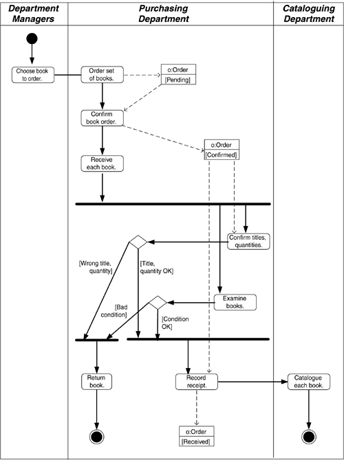
A sample activity diagram is shown in Figure 4.22. Note that activities are rounded boxes, and data flows are arrows, as we have seen before. In this case, there are three swim lanes, one each for the activities that are the responsibility of the Department Managers, the Purchasing Department, and the Cataloguing Department. The activities shown are the same as those previously shown for the examples of other modeling techniques.
Figure 4.22. UML Activity Diagram.

The treatment of data stores is very different from that in data flow diagrams. Whereas in the essential activity above, data stores are views, each typically composed of multiple entities, in a UML activity diagram, the only data stores are objects (entity occurrences). In fact, however, objects and classes in the object-oriented world are often called collections of what a relational model would declare as entity types. So the "objects" of the activity diagram are not that far removed from the views that are data flow diagram data stores.
Note that here a data store is not a class but a representative object (occurrence or instance) of that class. In Figure 4.22, the object labeled "o:Order" represents an instance of the class "Order", not the class itself. This is a subtle distinction not made in other modeling notations. This emphasizes the assertion that the model describes a set of actual objects, not simply an object structure. The expected state of that representative object after the action has taken place may also be indicated. Note that in Figure 4.22 this means the ORDER object appears once for each state (o:Order [pending], o:Order [confirmed], o:Order [received]). Among other things, this means that the object is repeated on the diagram for each state it may be in.
Note an interesting constraint: when flows diverge, this is denoted by a horizontal line; when they come back together again, there must be a matching horizontal line bringing together exactly the same number of flows that were divided above. This means that if there are successive divisions of flows, there must be successive convergence. Some activities may have to wait for the completion of others in the set.
The sample model in Figure 4.22 breaks out the receiving process more than in previous examples, to illustrate both the fork-and-join notation and branching. In the latter case, when the shipment is checked for correctness, it is either accepted and catalogued or returned.
Source: https://flylib.com/books/en/1.172.1.52/1/
Posted by: latashalatashadishmone0272247.blogspot.com